سمینار دیوار خاک مسلح
دیوار حائل

Analytical Method for Seismic Bearing Capacity of Stone-Column
Reinforced Shallow Foundations
Javad Nazari afshar
Mahmoud Ghazavi
khashayar hemmati
ABSTRACT
Stone-columns is a useful method for increasing bearing capacity and reducing settlement of foundation soil subjected to structure loading. For stone-column construction, 15 to 35 percent of weak soil volume is usually replaced with stone-column material. Such columns may be constructed with various diameters, lengths, and center-to-center distances. This paper presents a simple method to determine the seismic bearing capacity of stone-column reinforced shallow foundation. For this purpose, a simple failure surface is assumed to characterize the failure stage of the stone column and soil materials using the concept of lateral active and passive earth pressures. The well known Mononobe-Okabe approach is used to represent seismic effects of soil lateral earth pressures. The results show that with increasing the earthquake intensity, the foundation bearing capacity decreases. Parametric studies will be presented to illustrate the role of contributing parameters such as geotechnical data of stone column material, foundation geometry, native soil specification, and earthquake details
INTRODUCTION
The use of stone-columns is a useful method for increasing bearing capacity and also for reducing settlement of soil under structures. In stone-column construction, usually 15 to 35 percent of weak soil volume is replaced by stone-column that usually has a special diameter and length and center-to-center distance. Design loads on stone-columns normally vary between 20 to 50 tons. The confinement of stone-column material is provided by the lateral stress induced by the surrounding weak soil. Upon application of the vertical stress at the ground surface, the stone and soil move downward together, resulting in stress concentration in the stone-column due to higher stiffness induced into the stone material than that induced in the soil. Stone-columns are constructed usually in triangular pattern or sometimes in square pattern. The equilateral triangle pattern gives more dense packing of stone-columns in a given area as shown in Figure 1
Three type of failure mechanism may occur in stone-columns. These are bulging failure, shear failure, and punching shear failure. In end bearing or free floating stone-columns, bulging failure extends to or greater than about than three times the stone diameter in length (Huges et al., 1974 &1976). The shear failure mechanism occurs in very short columns resting on a firm support either a general or local bearing capacity type failure at the surface (Madhav et al., 1978). The punching
shear failure occurs in floating stone-column at a length of less than about two to three times the stone diameter. This failure type may occur in end bearing stone columns embedded in weak soil underlying layer before a bulging failure can develop (Aboshi et al, 1979)

Fig1. Equilateral triangle pattern of stone columns
In this research by using an “imaginary retaining wall assumption”, it has been tried to develop a simple analytical method for estimation of the seismic bearing capacity of stone-columns assuming bulging failure mechanism.
BULGING FAILURE MECHANISIM
Stone-columns have length to diameter ratios equal to or greater than 4 to 6 and are embedded in homogeneous soil, the bulging failure occurs at a depth of about 2-3 times the diameter of the stone-column. This failure type was explored by performing field tests on stone columns (Hughes et al., 1974). A number of theories have been presented for predicting the ultimate capacity of an isolated, single stone-column supported by soft soil. Most of the early analytical solutions assume a triaxial state of stress which exists in the stone-columns while both surrounding soil and the stone-column material are at failure. The lateral confining stress () which supports the stone-columns is usually taken in this methods as the ultimate passive resistance offered by the surrounding soil. This passive stage is reached upon mobilization of the stone-column bulges which occur outward against the soil. Since the column is assumed to be in a state of failure, the ultimate vertical stress () which the stone-column (stone-column assumes to be cohesion less) can tolerate is equal to the coefficient of passive pressure on the stone-column () times the lateral confining stress (). This means:
where is the internal friction angle of stone-column material.
A number of relations for estimation bearing capacity of stone-columns have been presented by Greenwood (1970), Vesic (1972), Hughes et al. (1974), Datye et al. (1975), and Madhav et al. (1979) in the form of . These relations are similar to Eq. (1). Most of researchers have only tried to enhance the ability and reliability of relations in predicting the surrounding confinement pressure () in Eq. (1). For example, Vesic (1972) introduced the following expression for determination of the ultimate lateral resistance of the soil:
where is cohesion of the surrounding soil and q is the mean (isotropic) stress at the equivalent failure depth, and are cavity expansion factors given in a graph as functions of the angle of internal friction angle of the surrounding soil and the rigidity index,. According to Vesic (1972), the rigidity index is expressed as:
where E is the modulus of elasticity of the surrounding soil in which cavity expansion occurs and is cohesion of the
surrounding soil, u is the Poisson’s ratio of surrounding soil, q is mean stress within the zone of failure.
In the above equations, in addition to the ultimate lateral stress () and some geotechnical parameter such as c and fc , other parameters such as the modulus of elasticity and Poisson’s ratio of the surrounding soil are also required to determine the stone column bearing capacity. In addition, all above methods consider the static ultimate bearing capacity of stone columns. The authors are unaware of any developed analytical methods to determine the seismic bearing capacity of stone columns. In this article, a very simple expression is developed for calculating the seismic ultimate bearing capacity of single stone-columns undergoing a bulging failure type only by having common shear strength parameters of soils. The developed method is simply used for static analyses as well .
NEW SIMPLE ANALYTICAL METHOD
An imaginary retaining wall (AB) is used for estimation the bearing capacity of shallow foundation rested on sand as shown in Fig. 2. An active zone beneath the footing on the left hand side of the wall and a passive zone on the right hand side of the wall are assumed. This method was first introduced by Richards et al. (1993) for determination of the bearing capacity of shallow foundations resting on a homogeneous sand.

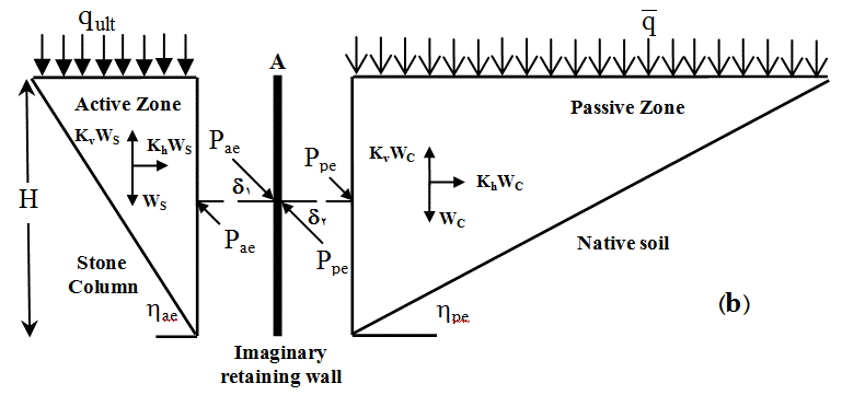
Fig2. Imaginary retaining wall conception
y:
دیوار حائل ژئوگریدی

STABILIZATION AND REINFORCEMENT OF SLOPE WITH GEOGRID
A CASE STUDY
Khashayar Hemmati
Seyed Vahid Masoomi
Javad Nazari afshar
ABSTRACT
This paper presents a case study example of appropriate method selection of stabilization and reinforcement of slope by introducing engineering and economical aspects. Introduced slope is located in science and research campus of Islamic Azad University (IAU) in north of Tehran with height of 4-29 m and length of 370 m. A big building with 9 floors and total area of 70000 square meters is located upper and near edge of slope, so that existence of this building has increased sensitivity of projects design and construction method. Slope is located in vulnerable area with a high risk of seismicity based of 6th Iranian building code. In addition primarily geotechnical site investigation is reported existing of 13 different geotechnical zones of rock mass with R.Q.D less than 10% and slope wash and fill material. A second expanded series of site investigations program have been performed to obtain better geotechnical resolution and information about slope. In this project, in addition of stabilization of slope, architectural aspects of slope’s stabilization system was very important, so that, capability of green face for slope and vegetate of small trees and grass in berms introduced in design, in addition slope should have a compliance with vicinity of existing project. By introducing of seismicity of project location and economy, stabilization and reinforcement of slope by geogrid material is selected for this project in comparison other excising methods. More detailed information about geological and geotechnical of site condition are presented in paper
INTRODUCTION
This paper presents a case study example of appropriate method selection of stabilization and reinforcement of slope by introducing engineering and economical aspects. Introduced slope is located in science and research campus of Islamic Azad University (IAU) in north of Tehran. The trench has a variable height about 4 to 29 meters and 370 meters length. There is a large 9 floors building above the trench with 70000 square meters area close to the edge of trench. The existence of this building forces a considerable surcharge in the trench. So this matter increases the sensitivity of the design and implementation method of this choice. According to the part sixth Iranian building code, the mentioned trench in that region is at the high risk seismicity. The required aim of this design is developing on appropriate place around the building (on the top slop) for mechanical equipment as campus of university. Architectural view of visual effects which is in accordance to the environment is of high importance. Developing vegetation in that area provides us a beautiful view plus stability. In figure 1, shows the related slope with project that building is on the top of slope. Fig.1 presents location of slope (highlighted) with buildings on top of the slope.
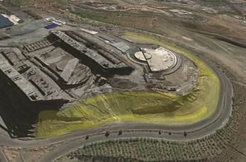
Fig.1. Location of slope
SITE INVESTIGATION
In the present project, achieving a good design directly depends on suitable program of site investigation and required
matter, four vertical bore holes in depth of 25 meters have excavated in the eastern area of this site which the results affect in the following items
Determine the physical quality of rock mass and its blocks
Determining thickness and type of surface layer
Determining the material properties of the fault zone
ANALYSIS
After completing the geological studies and required geotechnical testing, regarding the shown layers of soil logs and trench outcrops, have been specified that there are many changes in geometry layers of trench in depth and length which is prepared cross section perpendicular on trench at interval of 10 meters along the project appropriate to the geotechnical layering in each section for analysis of present slope. Limit equilibrium program (slide V.6) was applied for stability analysis. After reviewing all of the sections, it was specified that failure surface in most cases are in weak layer of slope wash (e.g. Blue layer in Fig. 2) and this layer should be removed for stabilizing of trenches
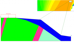
Fig.2. Stability analysis of slope before excavation
By introducing comprehensive site investigation program and gathering good information about geometry and direction of layers, it found that existing of slope wash layer has an essential effect on failure surface and FOS. Second series of analysis were performed on the slope by removing slope weak wash layer in all analysis. In Fig. 3 distribution of FOS along slope is presented
parameters for designing. Provided information about geological parameters by employer was very brief and incomplete. Therefore, the first step in achieving a proper survey about local investigation is determining more accurate parameters in geology and geotechnical design. The main structure by the trench from geological view is from highly weathered rocks (with RQD less than%10) which were unstable due to different pressure and variations in geological period and human intervention in excavation embankment. In General, the number of layers and geotechnical parameters of project is very various that part of project which has a highest height was of a very loose slope-wash that its depth is not specified in different places. In this regard, after boring several bore holes in different places and vast survey on geology and summarizing between achieved parameters in geotechnical parameters of rock units and soil, they categorized to 13 geological sections with special shear strength parameters for each zone
Table.1. Parameters of rock units and soil

Based on obtained soil logs from bore holes, the thickness and placement of each layers, in order to do the necessary analysis regarding computing slop stability and displace and finally achieving a general scheme. In order to realization of this
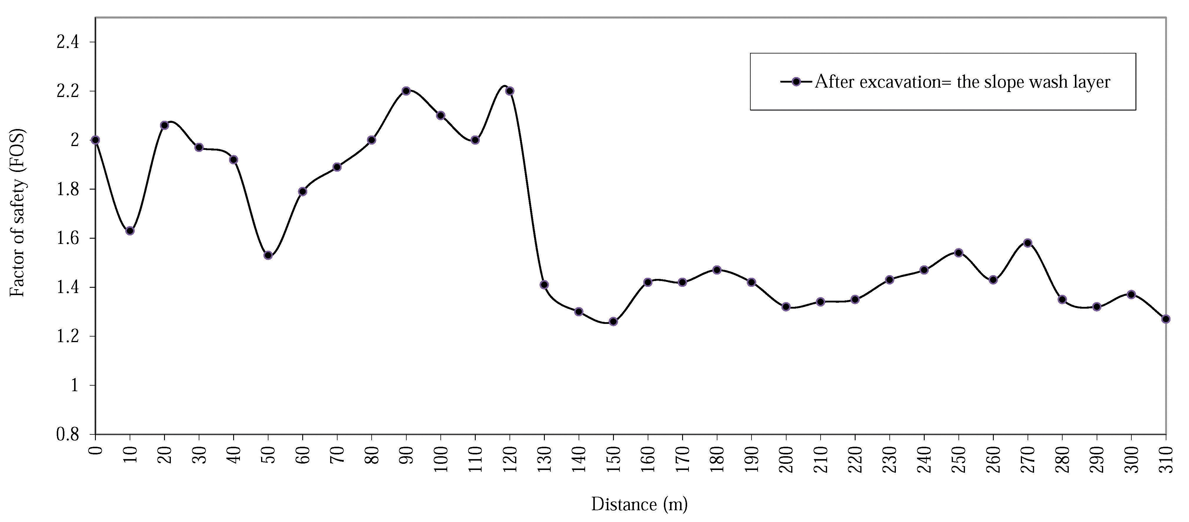
Fig.3. Distribution of FOS along slope length after excavation
METHODOLOGY & DESIGN
After specifying geometric & geotechnical properties of different parts of trench, it was required to survey different alternative for having a proper scheme that meet all the need of employer, in terms of stability & aesthetics and preserving the environment. After surveying of various options like retaining wall, anchor, nailing, the reinforced soil system is applied for stabilizing and embellishing the existence of slope. Regarding variation of safety factor in length of slope after removing slop wash layer, the project categorized to 3 section of geometrical reform of slope, making façade and reinforced soil system and mixture of those parts. Since embankment part is more determined than other parts, the main part of design allocated to this section and develop this part to others part. One of the benefit of reinforced soil system is that the major parts of soil which is as result of removing slop wash layer, is applied in reinforced soil system as a basic material. This matter is of vital important for reducing cost of soil displacement, fuel and damage to environment. It can be described the benefit of reinforced soil system in a summery as follow
Reinforced soil system is more economical in comparison to other retaining walls when average height of wall is greater than 3 m
Retaining wall of the reinforce soil system is so faster and easier to perform than other ways and there is no need to more labors and specialized equipment. Many components are prefabricated construction and lead us to a fast and exact performance.
Regardless to the height and length of wall, the structure of reinforced soil system is completely stable during performance
Reinforced soil system is more flexible in comparison to cantilever walls. So they are well known to more flexible retaining and can bear deformations and large settlement. While these kinds of displacement are anticipate embedding vertical joints facilitate any movement & displacement of wall. In this case of applying reinforced soil retaining, safety factor of soil bearing capacity will be reduced in comparison to conventional rigid retaining wall
Regarding the flexibility and property of energy absorbing integrated soil mass behind the wall; the seismic operation of reinforced soil system is better than rigid retaining walls. Totally, soil slippage of reinforced soil elements should be more considered in seismic design of reinforced soil retaining than their tensile strength
After choosing reinforce soil system as a selected design, regarding the limitation of the bottom & top slop of project and height variation, the 4 meters height and proper berm chosen for performing the reinforced soil retaining (Figure. 4) for green space and lighting

Fig.4.Veiw of Final design for slope
:CONCOLUSION
The real aim of this article was to convey this matter that taking more time on site investigation and obtaining more complete data by a supplementary test on geology and geotechnical, will be highly worth for engineers to choose the best options
In this project, achieving accurate data and taking a decision for replacing weak layer with a reinforced soil structure causes that the trench will be better in limited time from technical and engineering point of view
REFERENCES
FHWA. [2009]. “Design and Construction of Mechanically Stabilized Earth Walls and Reinforced Soil Slopes – Volume I
”. U. S. Department of Transportation Federal Highway Administration, Publication No. FHWA-NHI-10-024
FHWA. [2009]. “Design and Construction of Mechanically Stabilized Earth Walls and Reinforced Soil Slopes – Volume II”. U. S. Department of Transportation Federal Highway Administration, Publication No. FHWA-NHI-10-025
Bowles, J. E. [1988]. “Foundation Analysis and Design“. ۵th Ed., McGraw-Hill International Editions, Singapore